Selecting and Sizing Geared Motors
- Wednesday - 20/05/2020 10:06
- Close page
In this post, I’ll describe the process I use for sizing gearboxes and geared motors.
1. Consider the application requirements
Before you begin selecting a geared motor, you first need to consider and know the application requirements. This is not a comprehensive list but gives a general idea of the common considerations.
Torque & Speed
What torque and speed are required at the output of the gearing?
What does the typical torque profile look like?
Is the loading more or less steady – or will the gearing experience shock loading?
What electrical power do I have (three phase, 50 or 60Hz, Voltage)?
Duty
What is the duty of the application?
If I need more motor overload – can I rate for a reduced duty like S2 or S3?
Control
Does the application require position, torque or speed control?
Will the motor be run across the line or with a VFD?
Will the motor hold the load at 0 speed indefinitely (e.g. hoisting application)?
Does the motor need a spring-set brake on it?
Does it need a feedback device like an encoder?
Mounting
How will the gearmotor be mounted to the machine – foot mounted, shaft mounted, flange mounted?
Are there space constraints?
Does the output axis need to be inline or at a right angle
Environment
What environment is the gearmotor going into (e.g. caustic washdown, saltwater, sensitivity to noise, etc.)?
What are the ambient temperature ranges during operation?
Does it require special ingress protection (washdown, outdoors, etc.)?
Is this a food processing application that will require food grade lubricants and grease?

2. Select the correct gear technology for the application
Configurations in DOLIN start at the top left. On the left, you’ll see drop-downs to select different gear types and sizes.
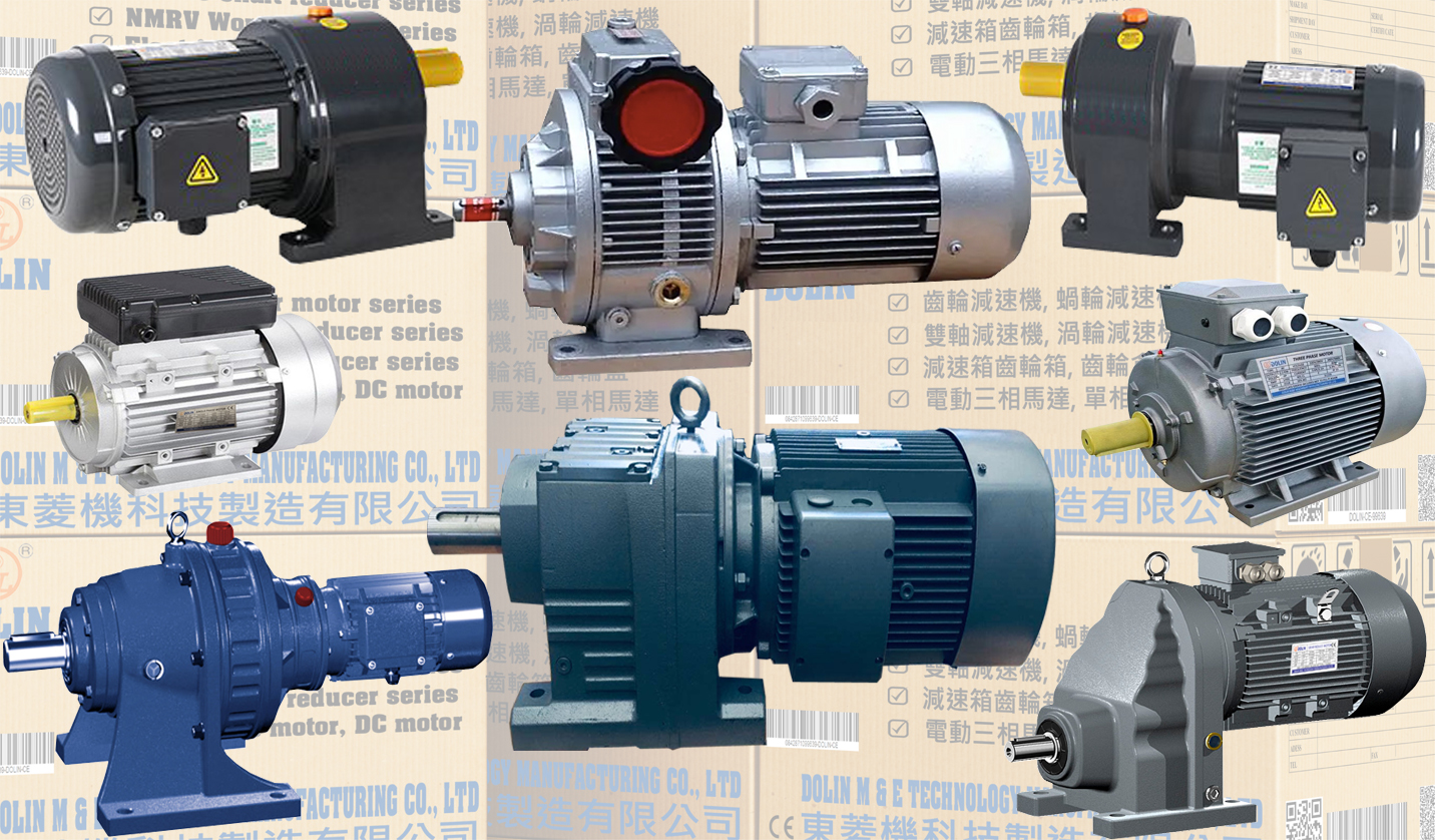
Dolin offers 4 main types of gearing:
4 Types of DOLIN Gearing
“Style” Gear Type Output Efficiency (%)
G Helical Inline 94-96%
F Helical Parallel Offset 94-96%
S Helical-Worm Right Angle 50-90%
K Helical-Bevel Right Angle 94-96%
Helical-Worm and Helical-Bevel will provide right angle outputs. Helical-worm can be cost advantageous for larger reduction ratios. Helical-bevel has the advantage of better efficiency, which can possibly equate to a smaller motor.
There is also an option available to leave off the gearing if are just interested in selecting a servo or induction motor.
3. Motor Selection (Size, voltage, frequency)
Working to the right, I then select the size of the motor I want. Options for both Induction motors and AC Servo motors are listed. Here is a comparison of the advantages between servo and induction motors.
There is a tab that allows you to select the stator winding information – specifically, the rated voltage and frequency. Dolin has the ability to offer special windings outside of what is listed.
Larger motors will provide more torque. As you increase the motor size, you’ll see the torque information is updated in torque/speed drop-down.
4. Adjust the Torque/Speed selection
Is it a speed reducer? Or a torque Increaser? It’s both – higher gear ratios will provide lower output speeds and higher torques. Use the drop down to see all the different possible configurations with the selected gearbox/motor combo.
Note: If you have selected a motor winding that is rated for both 50 and 60Hz, you will see two values listed for the speed and torque. The 50Hz rating will be reflected with the slower rpm output.
5. What is the gearing Service Factor and why is it important?
The gearing service factor (SF) is the ratio between the:

In other words, Service Factor provides a relative comparison to how much capacity the gears have in the current configuration.
A SF of 1.0 means the gears will have a nominal output torque equal to that of their rating. Selecting a motor/gear configuration with a SF of less than 1.0 is not advised. This means the gears will be undersized when operated at the nominal point. This could also indicate that the motor selected is too large.
Sometimes, the application is very difficult with regards to Duty, Shock loading, Temperature, etc. (look at step 1 – application requirements). In this case, it is advisable to select a very high SF which compensates for the factors that will stress, wear, and possibly damage the gearing.
Manufacturers typically provide a table of typical applications. Many also list a multiplication factor based on duty. Relatively easy applications like fans with light duty might have a SF closer to 1.0. It often becomes a trade-off between safety factor and cost.
At this point, if the selection is not able to meet the required torque, speed, and SF of the application, you’ll need to return to step 2 and select a different gear and motor combination. Or conversely, if the motor or gear appear to be oversized, then you can return to step 2 in order to optimize.
6. Select gearmotor options (mounting style)
This section allows a user to select how the geared motor will be mounted. The flexibility of mounting is one reason that the Dolin integral gearmotor solution has been so popular. Users can select a unit with an output shaft. Or a shaft mounted unit with a hollow bore. Mounting feet and mounting flanges can also be selected.
For shaft mount applications, a nice option is a shrink disk mounting. DOLIN’s shrink disc mounting provides a zero backlash connection between the gearbox and machine shaft. Assembly and disassembly are very easy.
To go along with the flexibility-theme, users can select either English or Metric units on the shaft/bores. If you don’t see the exact option you want in the configurator, then I suggest contacting a Dolin engineer to explore what is possible. We are able to offer a lot of customer flange and bore designs if the customer wants.
This section also includes the lubrication used in the gearbox. A number of different lubricants are possible depending on the application requirements.
Below that is a list of checkboxes that can be selected. Gearing options like low backlash and protection covers are possible.
7. Choose the motor options
This is where a user selects the motor options. Options like a motor on the brake. Or, the type of encoder for closed loop applications. Even the type of motor fan can be selected here.
8. General options
Next, the general options can be defined. These are special requirements that can be easily selected in the configurator. This includes a second nameplate, condensation drain hole, etc, The conduit box orientation and the fitting location are also defined here.
Finally, the paint treatment can be selected here. The number of applications and thickness of paint is defined. Consult the Dolin gearmotor catalog for the specifications. Added protection is possible with the P1, P2, or P3 options. These would be good options to consider for washdown, outdoor, and maritime gearmotor applications.
The paint color is also defined here. Gray and black are most commonly requested so they are standard options. But we can paint to whatever color the customer specifies. In the case of a special, contact DOLIN.
9. Gather 3D models and dimensional drawings
The last option is the mounting position of the gearmotor. This is important as it determines the oil fill level of the gearmotor and venting.

At this point, the user can explore additional tabs in DOLIN in order to get more information. Of note, the customer can get extra motor information including the efficiency values, nominal torque, and inertia values.
